Hi-WALL
The Infill Panel System forms a secondary structure that typically sits between each floor of the structural frame. It can be used to support a wide range of external finishes as well as the internal lining of the building.
The system primarily consists of stud, track and header sections which are held together using a range of tek fixings. Studs are typically positioned vertically at either 400mm or 600mm centres depending on the selected finishes. These are held in place at each end by a track and a header section which are connected to the main frame.
There is no need for cleats or brackets as sections are fixed together through overlapping flanges with a self drilling tek screw. These sections can also be used to form openings and trimmings within the frame to accommodate doors, windows and other penetrations that may be required.
Track Arrangements
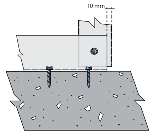
Track members are typically thin gauge lip-less channel sections that are used as a base for almost all wall frames. In most infill framing systems the track will be positioned along the edge of the slab/steelwork with frames spanning between floors allowing insulation and external finishes to run continuously outside the structural frame zones. Where required to achieve specific cladding zones or to accommodate any site tolerances, the track member can be stepped in or overhang the edge of the slab as required. For large overhangs additional support may be required.
Deflection Headers
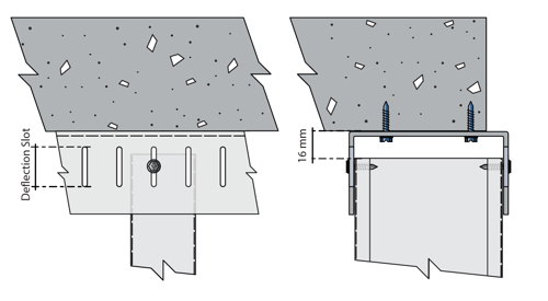
In order to accommodate deflections in the main frame, infill panels require a deflection header member that allows the main frame to move without compressing the stud sections. The Hi-WALL deflection header incorporates a slotted connection which when combined with the correctly detailed stud clearance allows for suitable movement at the top of each panel avoiding damage caused by compression in the studs or damage to the attached finishes.
When using a deflection header, finishes may also require clearance gaps or movement joints to avoid compression.
Clusters of five slots are punched at regular intervals along the deflection header to suit client requirements. Typically, standard bars are manufactured with slot clusters at spacings of 400mm or 600mm to suit the stud centres, which are cut to fit on site. Alternatively, clusters can be punched at any position along the length of the bar upon receipt of detailed drawings.
Please ensure that the tek fixing is positioned at the centre of the slot on the deflection header.
Fixing Dimensions
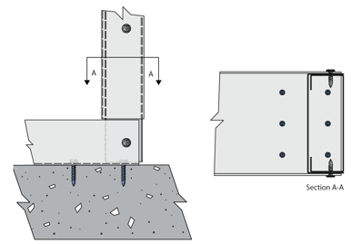
Tracks are fixed in place using either concrete screws or direct shot fired fasteners. These should be positioned at max. 600mm centres in a staggered arrangement. When using concrete screws, 7mm clearance holes can be pre-punched upon request within the track sections.
Stud Clearance
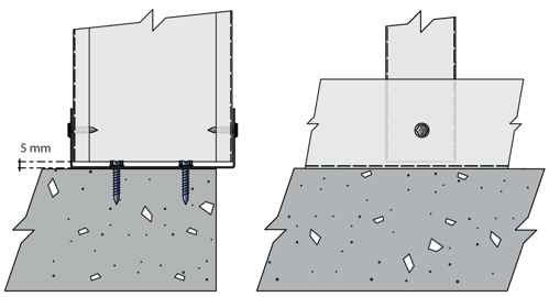
When detailing stud sections, we recommend a clearance dimension of 5mm from the track to accommodate tolerances within the slab.
The studs are connected via slotted cleats attached to the floor slabs/beams which are in place to accommodate the movement of the main frame. The base of the system requires support, usually through a track member fixed to the floor slab or additional hot rolled member.
As with infill panels, the studs are designed to carry lateral wind loads, along with the axial loads of the external cladding system.
The system can offer an increased speed of erection when using 150 deep sections and greater, as the studs can be supplied in up to 15m lengths.
Header and base rail sections can also be supplied as necessary to form a capping to the studs which may be needed as an additional fixing face for the cladding system.
Parapet Overhangs
When using the oversail system a parapet detail can easily be formed by continuing the stud section past the finished roof level. Closing the ends of these studs using a track member not only restrains the end of each stud but provides a fixing face for cladding panels and flashings.
Continuity Traks
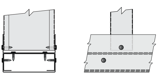
Where stud continuity between floors is required two track members are used to create continuity tracks. These members are fixed together back to back via pairs of tek screws through the webs creating a compound section.
The flanges of the formed section are then fixed to each of the finished rising studs, allowing the introduction of new studs above, this detail may be required a number of times on a multi-storey building.
Cleat Detailing
Cleats used within a oversail system are bespoke to each each project in order to suit the specific section sizes and cladding zones required. This dictates that the cleats for each project need to be detailed individually to achieve the appropriate offsets required.
All cleats require vertical slots to accommodate movement of the primary structure. Horizontal slots can also be incorporated to aid alignment of the cleat when fixing to the primary structure.
Base Track Supports
As this system sits outside the main frame consideration must be made about how the base track will be fixed. Unless this is considered at an early stage it is not always possible to extend the ground floor slab for the track to sit upon. In these situations an additional support angle running along the edge of the slab will need to be designed, or a purpose built brickwork plinth incorporated.
If none of these options are feasible or desired we would recommend the use of bespoke cleats. However, as these cleats will need to support the frame and its finishes these often need to be stronger cleats with more structural fixings back to the main frame or slab.
Cleat Variations
Cleats supporting Hi-Wall studs need to connect to a variety of primary structures. A degree of adjustment is required within the cleat design to enable accurate positioning of the cleats as they are typically installed on-site. Hi-Span offers a series which can be finely tuned to suit specific project requirements.
Hi-WALL members can form suitable jambs, sills and lintels for a wide variety of door and window openings. Our sections can be utilised either as single members or a compound section depending on the size of the opening to provide a suitable fixing face.
For guidance on suitability for a given project, please contact our Technical department.
The following table provides suitable fixing guidance for different Hi-WALL situations from our recommended manufacturers. Where project specific fixings have been designed, these will precedence over the general guidance. All the following recommendations are to be read in conjunction with the fixing manufacturers literature.